
Floor Plan Drawing Tools
Walls, rooms, doors, dimensions, snapping, fills and icons — the editor's full toolset.
The floor plan editor is a small CAD application. This article walks the toolbar. Set a scale first — see Floor plan editor basics — because the structure tools and the dimensions all work in real millimetres.
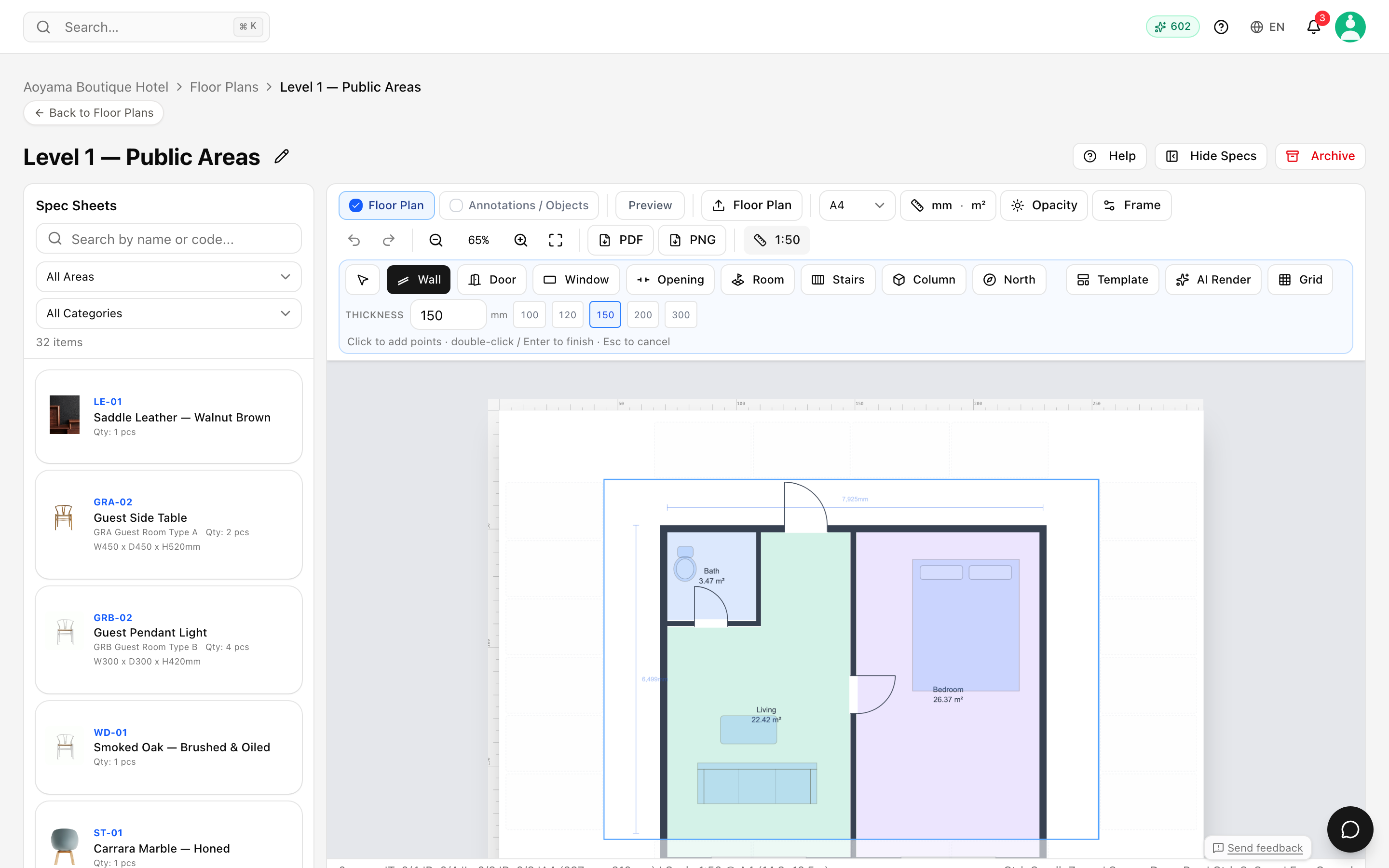
The toolbar has two rows. The top row picks a tool; the second row shows that tool's settings, or the settings of whatever you have selected. When nothing is active it reads Pick a tool or select an object — its settings appear here.
Structure tools
These draw a building, not just shapes. They all snap to each other and they all carry real dimensions.
| Tool | What it does |
|---|---|
| Wall | Click to add points, double-click or Enter to finish, Esc to cancel. Drag the round grips to move endpoints. Set Thickness in mm — type a value, or use the one-click presets 100 / 120 / 150 / 200 / 300 — and a Color per wall. |
| Room | Hover any enclosed area and click to fill it. A room carries a Room name and a Fill, and can show its area — turn on Show area on rooms. |
| Door | Placed on a wall. Styles: Single, Double, Sliding, Bi-fold, Pocket. Two buttons flip it and show its current state as their own label — Hinge: L / Hinge: R and Swing: In / Swing: Out. Width (mm) sets the opening. |
| Window | Placed on a wall, with Width (mm) and its own style list: Single, Double, Sliding, Casement. A window has no hinge or swing. |
| Opening | A wall break with no leaf — pass-throughs, cased openings. |
| Column | Click to place a structural post; snaps to wall corners. Set its width × depth in mm, and use the one button that toggles between Square and Round. |
| Stairs | A run of treads with an UP/DN arrow. Set Treads, Going and the up/down direction. |
| North | A north arrow — click to place, rotate to set north. |
| Grid | A 1 m grid with 250 mm snap. Needs a scale. |
A selected wall also offers Split into segments and Create room from wall.
Template opens Start from a template — a ready-made layout you can insert and adjust. An inserted template arrives as one group; Ungroup it to edit the individual walls, doors and rooms.
AI Render lets you drag a region of the plan and send it to AI Rendering, with the spec sheets in that region attached to the render.
Annotation and drawing tools
- Select and Pan.
- Rectangle, Circle, Line (hold Shift for a 45° snap; drag the endpoint grips to edit).
- Polyline — Enter or right-click to finish, Backspace removes the last point, clicking the start point closes the shape. A finished polyline can be switched between Open polyline and Close to polygon.
- Free Draw with an adjustable Brush Size.
- Text — click the canvas to place it. Then choose Font (Sans, Serif, Mono), Font size, Bold and Italic.
- Place Image — drop a photo or a drawing onto the plan (up to 20 MB).
- Highlight — a translucent area you can lay over part of the plan.
Dimension lines and snapping
Dimension Line draws a measured dimension between two points, and it snaps like a drafting program rather than guessing:
- A wall offers three snap lines — outer face, centreline and inner face — so you can take a dimension to whichever the drawing calls for.
- The closest candidate inside the tolerance wins, so those three lines can be picked apart even though they sit a few pixels from each other.
- Object edges, other dimensions and the page frame snap too.
Once drawn, a dimension is editable. Dimension Edit moves its endpoints (which re-snap as you drag), and dragging the number moves the label without touching the line. Label to the other side (left/right) and Label to the other side (up/down) flip the label across the dimension. Add leader line attaches a leader from the label to the thing it describes; Remove leader line takes it off. Dim opacity fades dimensions back when they crowd the drawing.
Right-click an object and choose Size annotation for an associative dimension pair: a W dimension above the object and an H dimension beside it, both linked to it. Move or resize the object and the annotations follow and re-measure themselves. Drag an annotation to change its stand-off distance and that offset is kept.
Fill, stroke and text style
Fill & Stroke sets Fill Color (or No fill), Stroke Color (or No stroke), Stroke Width and Opacity for the selection. The same controls sit inline in the second toolbar row while an object is selected, so you rarely need to open the popover.
Arranging objects
- Group (Ctrl+G) and Ungroup.
- Bring to Front and Send to Back.
- Lock/Unlock — freeze something you've finished with so you stop nudging it.
- Rotate 90°, Flip horizontal, Flip vertical.
- Edit Pts — edit a polyline's points; double-clicking the shape does the same.
- Duplicate, Delete (Del), Select Similar and Select All from the right-click menu.
Icons and presets
Furniture Presets is a library of plan symbols — tables, chairs, beds, sanitary ware — that drop in at the right size for your scale.
Presets arrive in a standard fill and stroke. To draw a whole plan in your own convention, set the colours you want in Fill & Stroke and press Set as Preset Default — every preset you place afterwards uses them for the rest of the editing session. Reset to Default goes back to the standard style.
Custom Icons holds your own symbols — + Upload SVG adds one. Icons are stored per project, which the heading spells out as Custom Icons (Project): an icon you upload here is available on every plan in this project, and only in this project. Upload your studio's standard symbols once per job.
Exporting
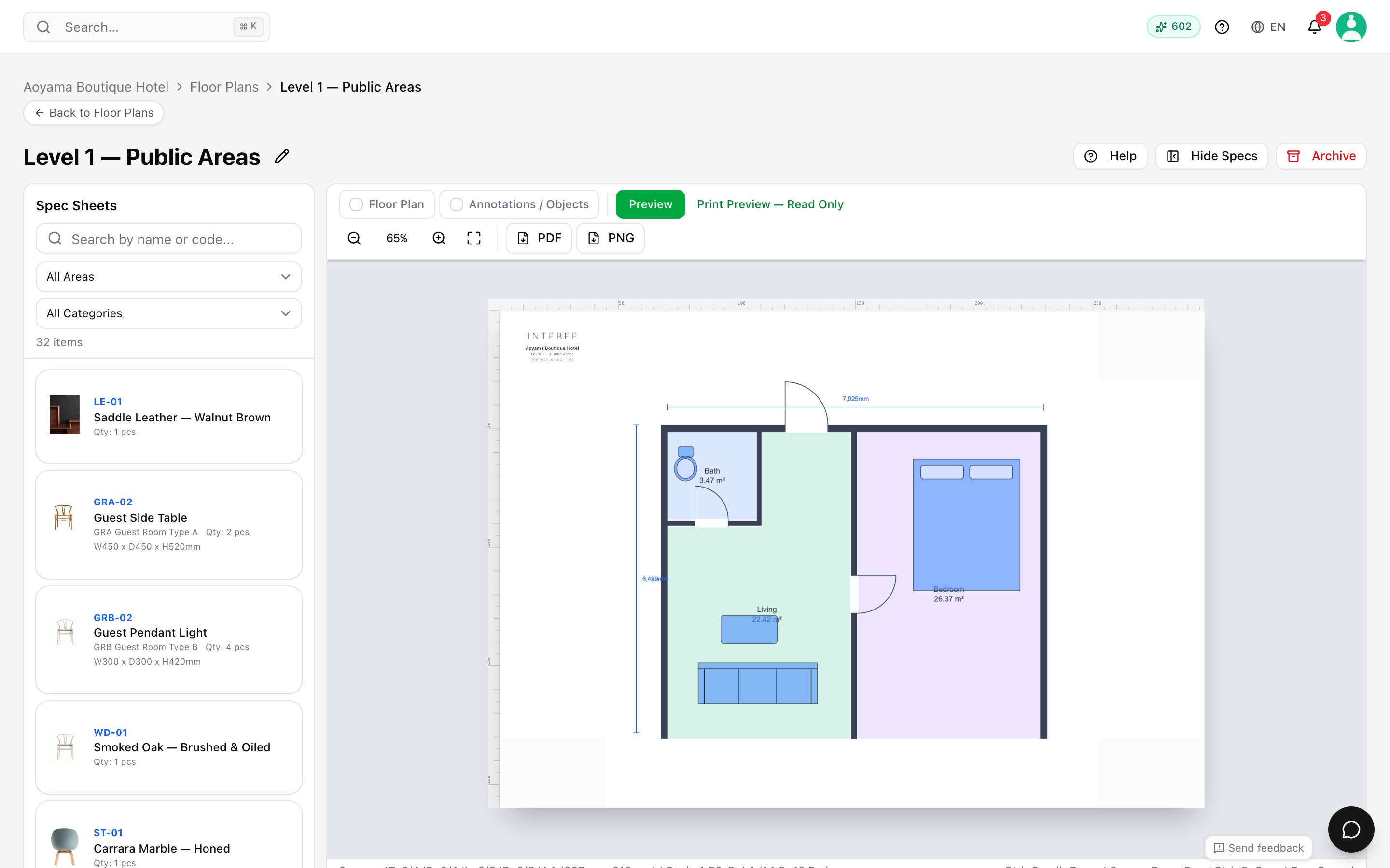
Export PDF and Export PNG both render the frame, the spec slots and the placed item codes. See Floor plan editor basics.
Related
- Floor Plan Editor Basics — creating plans, scale, frame, export
- Placing Items on Floor Plans — linking the drawing to your spec sheets